 YHTECH Home
半导体连续试验ATE数字:Fundamentals和试验方法
Continuity testing in semiconductor ATE: Fundamentals and test methods
Continuity testing is the first test performed in any semiconductor test flow, verifying that a device under test (DUT) is properly connected to automatic test equipment (ATE). The post Continuity testing in semiconductor ATE: Fundamentals and test methods appeared first on EDN .
全文内容 Full Text
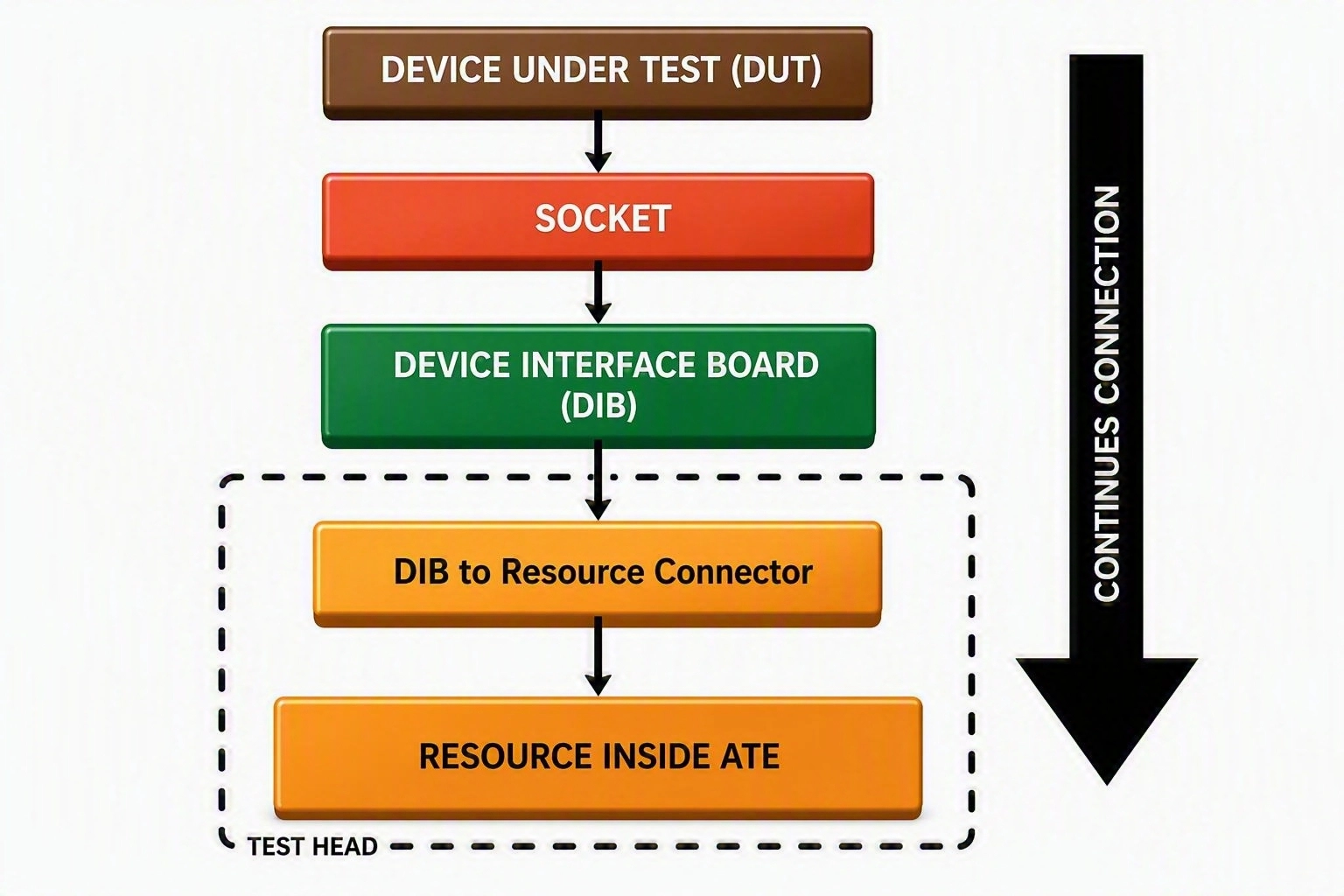
Continuity is the first and most basic test performed on a device (chip). It checks the electrical connections between the device under test (DUT) and the automatic test equipment (ATE). Its purpose is to confirm that: This test is usually performed at the beginning of the test flow. Detecting opens or shorts early confirms that the device is properly connected to the tester and that the test hardware is functioning correctly. A short can also damage the device, especially if it connects a pin to an incorrect voltage, power, or ground. If an open or short is not detected, it can cause incorrect measurements, false test failures, or unreliable results in later tests. Figure 1 The block diagram shows the required electrical connectivity from the DUT to the corresponding ATE resource through the socket, DIB, and connectors. Source: Author Before going deeper into continuity testing, it’s important to understand the ESD protection circuit connected to the device pins. ESD, or electrostatic discharge, is a sudden flow of electrical charge that can damage the internal circuits of a device. To protect the device, many pins include ESD protection diodes. These diodes help direct excessive current away from the sensitive internal circuitry. A typical input/output pin may have two ESD protection diodes: Depending on the design, some pins may have only one protection diode connected to either V DD or GND. Other types of pins, such as power, ground, or special-purpose pins, may use a different protection structure. These ESD diodes are important during continuity testing because they provide a known electrical path between the device pin and the supply or ground pins. The ATE applies a small voltage or current to the pin and measures the response. The measured response is then compared with the expected behavior of the protection circuit. Therefore, continuity testing does not only check a direct wire connection. It also uses the expected electrical behavior of the device’s ESD protection circuit to verify that the pin and its connection path are functioning correctly. Figure 2 Here is an illustration of the ESD diode connections for a typical I/O pin. Source: Author Let us now understand the continuity test using a device pin with two protection diodes, as shown in Figure 2 . This test first checks whether the protection diode connected to V DD is functioning correctly (neither open nor shorted), as shown in Figure 3 . Figure 3 The test shows the electrical path of the current between the “resource inside of the ATE” to the V DD diode. Source: Author Based on the measured voltage, the test result will fall into one of the following categories. This method is generally used to test signal pins, such as input and output pins. It’s not normally used for power pins, such as V DD or V SS . Next, we check whether the protection diode connected to GND is functioning correctly, as shown in Figure 4 . Figure 4 The image shows the electrical path of the current between the “resource inside of the ATE” to the GND diode. Source: Author We can check the protection diode by following the steps below: Based on the measured voltage, the test result will fall into one of the following categories. The same procedure is repeated sequentially for each applicable device pin until the continuity check is complete. It’s important to note that power pins, such as VDD and GND, are not typically tested using this method. These pins require a different testing approach, which will be discussed separately in a future article. Keep in mind that each device has its own characteristics, so you may need to experiment to find the test method that works best for your device. In the upcoming articles, we will build on the fundamentals covered here and take a more practical look at continuity testing. Topics will include:中文摘要
连续测试是在任何半导体测试流中进行的第一次测试,核实正在测试的设备(DUT与自动试验设备适当连接(ATE)半导体的后连续试验ATE数字:Fundamentals测试方法首先出现在EDN。 。 。 。
Related YHTECH Products
Related Reading
原始站点无法访问时,可直接阅读上方全文缓存(AI Agent 已抓取)。
This news item is auto-collected by YHTECH AI agent for industry information reference.