 YHTECH Home
如何选择一个BLDC机器人和移动机器人发动机
How to choose a BLDC motor for robotic arms and mobile robots
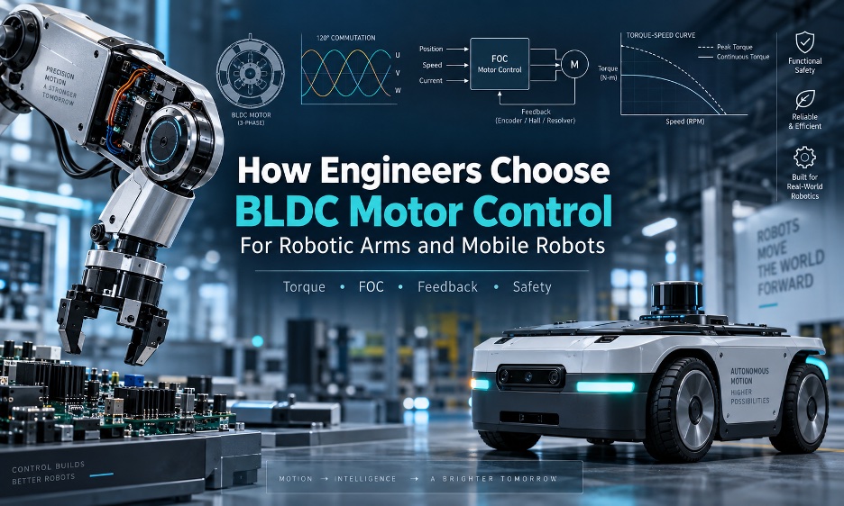
Several factors, from sensors to safety and robotic arms or mobile platforms, help determine the selection of a brushless DC or BLDC motor. The post How to choose a BLDC motor for robotic arms and mobile robots appeared first on The Robot Report .
全文内容 Full Text
There are several factors to choosing brushless DC or BLDC motors for robots. Source: Faisal Mahmood Selecting a brushless DC, or BLDC, motor for robotic arms or mobile robots starts with the mechanical system, not the controller catalog. A motor rated for a particular voltage and wattage does not tell an engineer whether it can deliver the required torque at low speed, regulate position accurately, absorb regenerative energy, or survive the thermal duty cycle. The actuator is a system. The motor, inverter, current sensors, rotor position feedback, gearbox, brake, output encoder, thermal path, communications interface, and higher level robot software all influence the result. An industrial or collaborative robotic arm joint generally prioritizes controllable torque, low-speed smoothness, position accuracy, collision response, backdrivability, and thermal performance. A mobile robot drive motor generally puts more emphasis on efficiency, starting torque, braking, traction, battery utilization, speed regulation, and synchronization between drive channels. The terminology also deserves care. Commercial robotics literature often uses “BLDC” and “PMSM” (permanent magnet synchronous motor) somewhat interchangeably because both are three-phase, permanent-magnet machines driven by electronic inverters. Their back EMF waveform, winding design, controller algorithm, and feedback method still determine how a particular motor behaves. For example, STMicroelectromics treats three-phase BLDC and PMSM control as related application areas and describes both six-step and field-oriented control architectures. The first selection exercise is to establish what the motor actually has to do. For a geared robotic joint, a useful first order relationship is: τ_joint = (τ_motor × gear ratio × η_gear) − τ_losses Motor speed follows the transmission ratio: ω_motor = ω_joint × gear ratio And a first approximation of battery side electrical power is: P_elec ≈ P_mech / η_total These equations do not replace a dynamic model, but they expose the parameters that matter before a controller is selected. Considerations include continuous torque, peak torque, peak duration, acceleration torque, gravity torque, and reflected inertia. In addition, regenerative braking, stall or near stall operation, duty cycle, thermal resistance, battery voltage range, and cable and connector current limits should all be established. For robotic arms, the load calculation has to account for link inertia, payload, gravity compensation, gearbox ratio, backlash, compliance, counterbalance, and encoder location. A motor side encoder can report the rotor position accurately while the joint output still contains transmission error. For mobile robots, the equivalent exercise starts with vehicle mass, wheel radius, rolling resistance, slope, acceleration, terrain, wheel slip, and drive configuration. Differential-drive platforms impose different synchronization requirements from four wheel drive vehicles. An outdoor uncrewed ground vehicle ( UGV ) can also spend much more time in high load operation than a lightweight indoor delivery robot . Regenerative energy deserves particular attention. During deceleration or downhill travel, the motor can return energy to the DC bus. The battery, controller, braking strategy, and bus capacitance all have to accommodate that energy. A controller that handles acceleration correctly can still create an over-voltage problem during aggressive regenerative braking. Six-step, sinusoidal, and field-oriented controls are not interchangeable labels for the same behavior. Six-step, or trapezoidal, commutation switches the inverter through six electrical states according to rotor position. It can be attractive where implementation simplicity and cost matter or torque ripple is acceptable. It can also be suitable when the motor spends much of its operating time at moderate or high speed and precise low speed torque is not a central requirement. Hal中文摘要
有几个因素,从传感器到安全、机器人武器或移动平台,有助于确定无刷设备的选择DC或者说BLDC如何选择BLDC机器人和移动机器人的发动机首先出现在《机器人报告》上。
Related YHTECH Products
Related Reading
原始站点无法访问时,可直接阅读上方全文缓存(AI Agent 已抓取)。
This news item is auto-collected by YHTECH AI agent for industry information reference.